
Portable Water Treatment Plant
Company: BioDAF Water Technologies
Project Type: Industrial Design / Product-Service System Design
Timeline: (March 2018– September 2018)
Role: Industrial designer, 3D modeler, Drafstman
Tools Used: SolidWorks, KeyShot, AutoCAD, Adobe Suite
Problem Statement:
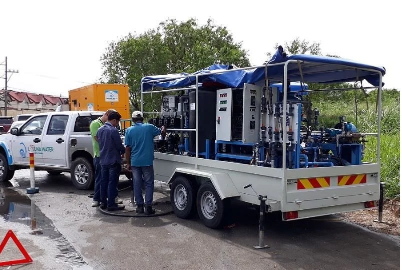
Develop a cost-effective and transportable water treatment solution that can be quickly deployed in remote or temporary locations, while utilizing existing 40-foot shipping containers available on-site and operating within strict budget constraints.
BioDAF Water Technologies is an environmental engineering company specializing in advanced wastewater treatment solutions. They design and build compact dissolved-air flotation systems for municipal, industrial, and landfill applications, helping clients remove pollutants and recycle water efficiently. With a focus on sustainability and custom-engineered systems, BioDAF delivers cost-effective and high-performance treatment technologies.
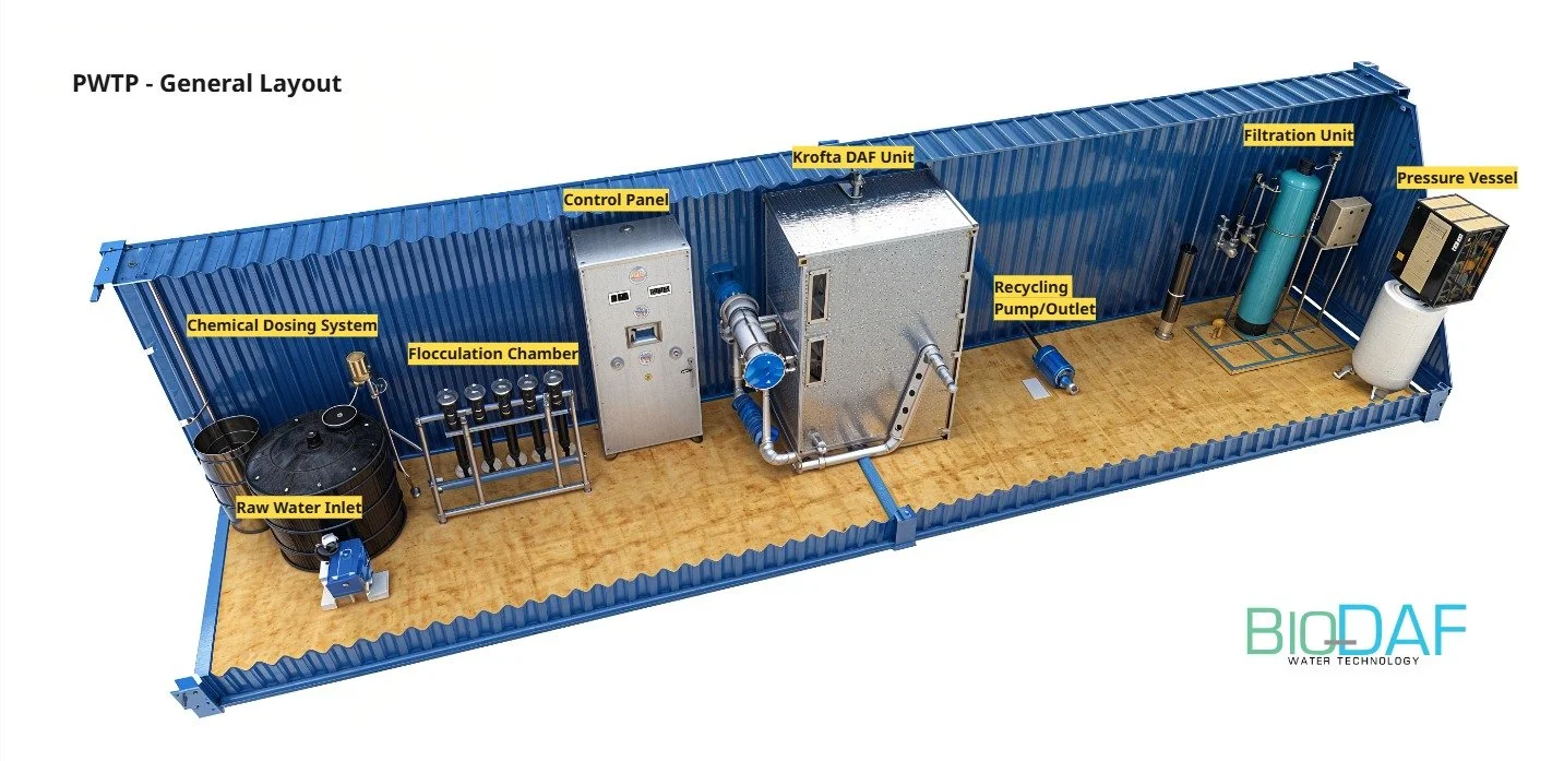
This case study explores the design and development of a portable water treatment plant for remote and temporary deployment. Undertaken during my time at BioDAF Water Technology, the project addressed several real-world constraints, including a limited budget and the client's request to repurpose surplus 40-foot shipping containers already available on-site.
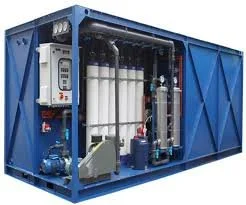
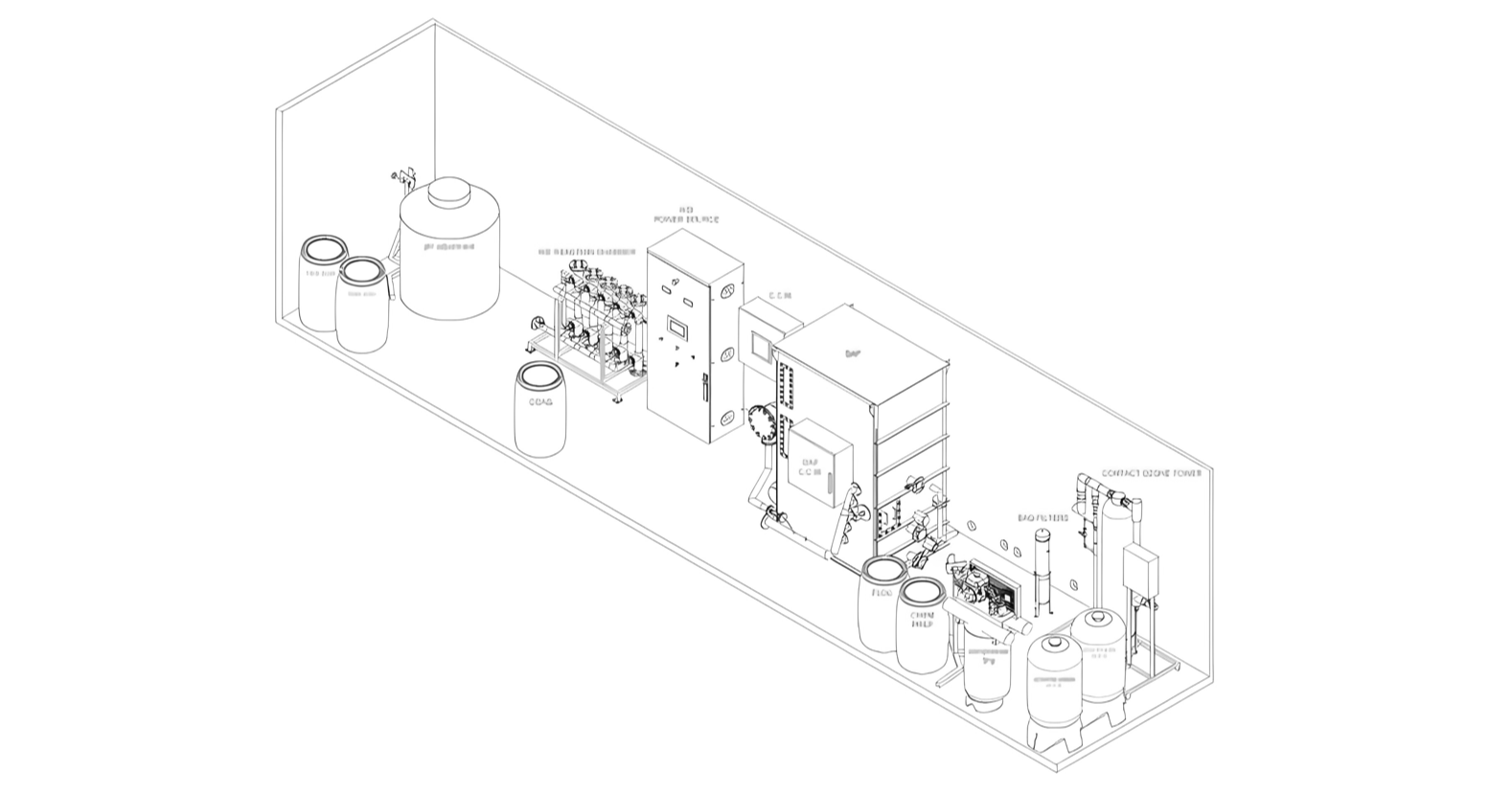
The solution involved engineering a fully functional treatment system within the fixed dimensions of the container. The final 3D model highlights an efficient layout of key components—such as a dissolved air flotation (DAF) unit, filtration system, chemical dosing equipment, and control panel—while ensuring ease of transport, installation, and operation.
Due to confidentiality clauses, the client cannot be named, but it is a construction-sector company specializing in remote site operations in arid environments.
Introduction

1. Design & Integration
Research & Technical Understanding
Develop a fully integrated water treatment system within the dimensions of a 40-foot shipping container.
Ensure inclusion and proper spatial arrangement of all critical components, such as:
Dissolved Air Flotation (DAF) unit
Filtration system
Chemical dosing equipment
Water Tanks
Pumps
2. 3D Modeling & Visualization
Create a highly detailed 3D model that accurately represents the engineering and layout of the system.
Use realistic rendering techniques to highlight materials, structure, and equipment arrangement.
3. Functionality & Usability
Optimize the model for ease of transportation, installation, and operation in remote or temporary environments.
Reflect real-world constraints such as accessibility, maintenance space, and safety.
4. Communication & Presentation
Deliver the model as a visual aid for client presentations, proposals, and stakeholder discussions.
Support project planning and decision-making by providing a clear, visual understanding of the plant layout and operation.
5. Context of Use
Tailor the system for use in temporary deployments, disaster relief, industrial sites, or rural areas with limited water infrastructure.
Project Scope


Industry examples

Approach & Process

1. Research & Technical Understanding
To begin, I collaborated with the engineering team at BioDAF to fully understand the functionality and spatial requirements of each system component, including the DAF unit, filtration modules, chemical dosing tanks, and control systems. This technical grounding ensured the 3D model would reflect real-world constraints and operational workflows.


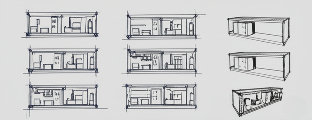
2. Sketches & Spatial Planning
Early hand-drawn sketches and layout diagrams were created to explore possible spatial configurations within the 40-foot container. These helped in visualizing equipment placement, maintenance access, and flow direction. A key challenge here was fitting all components without compromising usability or safety.
What worked: Starting with basic sketches allowed quick iteration before committing to detailed modeling.
What didn’t work: Some early layouts failed to account for operator access and pipe routing, leading to impractical configurations.
3. 3D Wireframes & Draft Models
Once a workable layout was established, I developed a wireframe model in CAD to test spatial fit, clearance, and connectivity between components. These early drafts helped identify bottlenecks in the workflow—like awkward chemical tank placement and insufficient clearance for the DAF unit’s maintenance.
Struggles: Ensuring realistic pipe runs and utility access within tight spaces required multiple reworks and input from engineers.
Decision rationale: I prioritized accessibility and modularity, even if it meant slightly reducing equipment redundancy to ensure ease of use and maintenance.


4. Realistic Rendering & Optimization
With the layout finalized, I added textures, lighting, and environmental context to produce realistic renders. I carefully balanced visual fidelity with performance to make the model suitable for both static presentation and interactive walkthroughs.
What worked: Emphasizing clean visuals and a clear hierarchy helped non-technical stakeholders understand the system.
What I learned: The power of visualization in bridging the gap between technical complexity and client comprehension is immense.
5. Iteration Based on Feedback
After presenting the first renderings, I incorporated feedback from sales, engineering, and project management teams to refine equipment labels, improve visibility, and add exploded views for clarity.
Final Deliverables
1. Technical Drawings and Schematics
2. 3D Renderings and Visualizations
3. Bill of Materials (BOM)
4. System Performance Specifications
5. Manufacturing and Assembly Guidelines
6. Operational Manual / User Guide
7. Compliance and Certification Documents
8. Design Rationale and Project Report


This project was developed under a Non-Disclosure Agreement (NDA) with the client, which legally prohibits the sharing of proprietary content, technical details, and visuals related to the system.
The deliverables contain intellectual property, confidential engineering solutions, and client-sensitive strategies that are protected to maintain their competitive edge and product integrity.
The content shown here is limited to what is permitted under the NDA.
Conclusion
This project successfully delivered a practical and visually compelling solution for portable water treatment under real-world constraints. By repurposing existing 40-foot shipping containers and working within a limited budget, the design achieved both functional efficiency and spatial optimization. The detailed 3D model supported client presentations, internal planning, and served as a valuable communication tool across teams. Additionally, the comprehensive CAD plans were instrumental in guiding the precise on-site installation of components, minimizing errors and improving setup efficiency.
While the final design prioritized function, cost, and ease of deployment, the project also highlighted opportunities for future development. Without the constraints of budget and reliance on pre-existing container dimensions, a more stylized and customized version of the system could be explored—enhancing aesthetics, branding, and user interaction without compromising performance. Overall, the project demonstrated how thoughtful design, informed by real-world limitations, can still lead to effective, innovative, and scalable solutions.
Summary of Key Lessons:
Technical accuracy must be balanced with visual clarity. Cross-disciplinary feedback is essential. Containerized design requires creative spatial problem-solving

Core Performance KPIs
2. Filtration / Membrane Flux Rate
The volume of water that passes through membrane surface per unit time and area — measured in LMH (liters per square meter per hour).
Target for clean influent from Krofta DAF + UF system:
➤ 60 LMH
1. Recovery Rate
percentage of feedwater successfully processed into usable treated water, accounting for system losses like sludge or cleaning backwash.
Target for Krofta-style portable units (optimized, low-waste design):
➤ 95% recovery rate
3. Energy Consumption / Energy Intensity
The total electricity used per cubic meter (or per 1,000 gallons) of treated water — includes pumps, air saturator, mixing, and instrumentation.
With membrane filtration (UF or RO):
➤ Add 0.8–1.5 kWh/m³ (RO is more energy-intensive)